Hardware
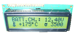
I used a simple 16x2 character LCD Display based on a popular Hitachi HD44780 compatible controller chip.
Concretely I bought an EW162G0 from ChipCAD.hu by less then 4 Euros!
I used an other datasheet/documentation for development, which text belongs to an other LCD Display. It was necessary, because it was very important to know everything about the device, and the chip of these displays are the same. You can << DOWNLOAD ITS FULL DATASHEET HERE >>

Specification
- Pin assignment
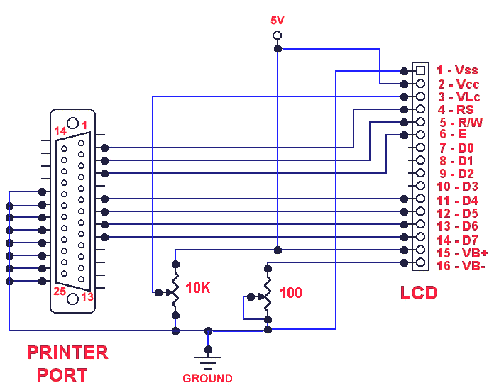
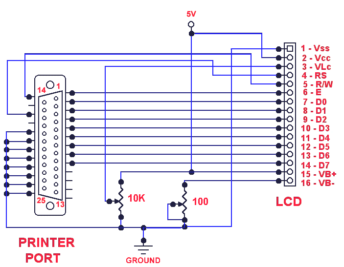
Pin No. On LCD Pin No. On LPT port. 1 VSS (+5V) - - 2 VDD (Ground) 18-25 Ground 3 V0 (Contrast) - - 4 RS (Register Select) 2 DB0 5 RW (Read or Write) 3 DB1 6 Enable (Data Ready Signal) 4 DB2 7 DB0 - - 8 DB1 - - 9 DB2 - - 10 DB3 - - 11 DB4 6 DB4 12 DB5 7 DB5 13 DB6 8 DB6 14 DB7 9 DB7 15 VLED+ (Backlight) - - 16 VLED- (Backlight) - -
- To see the text on the display, you need to add a 10k resistor as follows.

- This device has a 4-bit and an 8-bit operation mode which depends on the initialisation
(as you can see in the driver). Because 8-bit mode uses 11 pins, it is necessary to use the 4-bit
mode with our LPT port.
- Enable line indicates the controller ready to transmit data when it goes to 0 from logic 1.
- RS line indicates whether data or instruction is provided by the user.
- RW line indicates whether we are reading from or writing to the LCD device.
- DB0 - DB3 are not used in 4-bit mode.
- DB4 - DB7 used in both cases. By using 4-bit mode, we should transmit 8-bit datas in two parts.
- Following commands are implemented in the HD44780 compatible controllers:
- Clear display
- Return cursor to home ( pos 0,0 )
- Display On/Off
- Cursor/Display shift
- Function set
- Set CGRAM address (character generator)
- Set DDRAM address (data ram)
- Read busy flag and address (flag eliminable by using correct delays in driver)
- Write data to RAM (either CGRAM or DDRAM)
- Read data from RAM (either CGRAM or DDRAM)
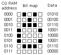
- CGRAM contains the character bitmaps whiches can be displayed.
The character map is the standard english ascii as we will see later.
The bitmaps of first 8 characters can be redefined by their new bitmaps.

4-bit mode wiring

8-bit mode wiring (not supported in the driver)
